
Transformer ON Load Condition:
When the transformer is on load condition, that means the secondary of the transformer is attached with some load, either it can be resistive, inductive or capacitive. Current I2 flows through the secondary winding of the transformer. The magnitude of the current I2 depends upon the terminal voltage V2 and impedance of the load. The phase angle depends upon the nature of the load.
Contents:
Operation of the Transformer on Load Condition:
The Operation of the Transformer on Load Condition:
When the transformer is on NO load, it draws no load current I0. This no load current produces an MMF N1I0 which sets up the flux ϕ in the core as shown in the figure below

When the transformer is loaded, current I2 flows in the secondary winding as shown in the figure below. This secondary current I2 produces an MMF N2I2, which sets up the flux ϕ2 in the core. This flux ϕ2 opposes the flux ϕ which is set up by the current I0. (According to Lenz’s law).
Definition of Lenz's law:
Lenz's law states that when an emf is generated by a change in magnetic flux according to Faraday's Law, the polarity of the induced emf is such, that it produces an current that's magnetic field opposes the change which produces it.
The negative sign used in Faraday's law of electromagnetic induction, indicates that the induced emf ( ε ) and the change in magnetic flux ( δΦB ) have opposite signs.

Where,
ε = Induced emf
δΦB = change in magnetic flux
N = No of turns in coil

Since the flux ϕ2 opposes the flux ϕ the resultant flux tends to decrease and causes the reduction of self-induced emf E1. Thus, V1 predominates over E1 causing additional primary current know as I1’drawn from the supply.The amount of the additional current is such that the flux in the core must be restored to its original value ϕ, so that V1 = E1. The current I1’ is in phase opposition with I2 and is called Primary Counter Balancing Current.
This additional current I1’produces an MMF, NI I1’ which sets up flux ϕ1’. The direction of the flux ϕ1’ is same as the flux ϕ and it cancels the flux ϕ2 sets up by the MMF N2I2.
Now, N1I1’ = N2I2
Therefore,

The phasor difference between V1 and I1 gives the power factor angle ϕ1 of the primary side of the transformer.
The power factor of the secondary side depends upon the type of load connected to the transformer.
If the load is inductive as shown in the above phasor diagram, the power factor will be lagging, and if the load is capacitive the power factor will be leading.The total primary current I1 is the vector sum of the current I0 and I1’.
i.e

Phasor Diagram of Transformer on Inductive Load:
The phasor diagram of the actual transformer when it is loaded inductively is shown below

Steps to draw the phasor diagram:
Similarly
Phasor Diagram of Transformer on Capacitive Load:
The Transformer on Capacitive load is shown below in the phasor diagram.

Steps to draw the phasor diagram at capacitive load:
When the transformer is on load condition, that means the secondary of the transformer is attached with some load, either it can be resistive, inductive or capacitive. Current I2 flows through the secondary winding of the transformer. The magnitude of the current I2 depends upon the terminal voltage V2 and impedance of the load. The phase angle depends upon the nature of the load.
Contents:
- Operation of the Transformer on Load Condition
- Phasor Diagram of Transformer on Inductive Load
- Steps to draw the phasor diagram
- Phasor Diagram of Transformer on Capacitive Load
- Steps to draw the phasor diagram at capacitive load
Operation of the Transformer on Load Condition:
The Operation of the Transformer on Load Condition:
When the transformer is on NO load, it draws no load current I0. This no load current produces an MMF N1I0 which sets up the flux ϕ in the core as shown in the figure below

When the transformer is loaded, current I2 flows in the secondary winding as shown in the figure below. This secondary current I2 produces an MMF N2I2, which sets up the flux ϕ2 in the core. This flux ϕ2 opposes the flux ϕ which is set up by the current I0. (According to Lenz’s law).
Definition of Lenz's law:
Lenz's law states that when an emf is generated by a change in magnetic flux according to Faraday's Law, the polarity of the induced emf is such, that it produces an current that's magnetic field opposes the change which produces it.
The negative sign used in Faraday's law of electromagnetic induction, indicates that the induced emf ( ε ) and the change in magnetic flux ( δΦB ) have opposite signs.
ε = Induced emf
δΦB = change in magnetic flux
N = No of turns in coil

Since the flux ϕ2 opposes the flux ϕ the resultant flux tends to decrease and causes the reduction of self-induced emf E1. Thus, V1 predominates over E1 causing additional primary current know as I1’drawn from the supply.The amount of the additional current is such that the flux in the core must be restored to its original value ϕ, so that V1 = E1. The current I1’ is in phase opposition with I2 and is called Primary Counter Balancing Current.
This additional current I1’produces an MMF, NI I1’ which sets up flux ϕ1’. The direction of the flux ϕ1’ is same as the flux ϕ and it cancels the flux ϕ2 sets up by the MMF N2I2.
Now, N1I1’ = N2I2
Therefore,
The phasor difference between V1 and I1 gives the power factor angle ϕ1 of the primary side of the transformer.
The power factor of the secondary side depends upon the type of load connected to the transformer.
If the load is inductive as shown in the above phasor diagram, the power factor will be lagging, and if the load is capacitive the power factor will be leading.The total primary current I1 is the vector sum of the current I0 and I1’.
i.e
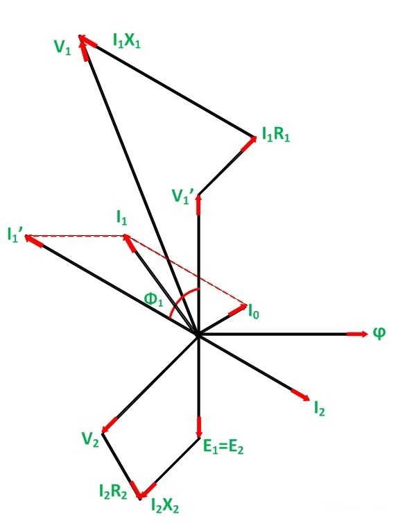
Phasor Diagram of Transformer on Inductive Load:
The phasor diagram of the actual transformer when it is loaded inductively is shown below

Steps to draw the phasor diagram:
- Take flux ϕ a reference
- Induces emf E1 and E2 lags the flux by 90 degrees.
- The component of the applied voltage to the primary equal and opposite to induced emf in the primary winding. E1 is represented by V1’.
- Current I0 lags the voltage V1’ by 90 degrees.
- The power factor of the load be lagging. Therefore current I2 is drawn lagging E2 by an angle ϕ2.
- The resistance and the leakage reactance of the windings result in a voltage drop and hence secondary terminal voltage V2 is the phasor difference of E2 and voltage drop.
- V2 = E2 – voltage drops
- I2 R2 is in phase with I2 and I2X2 is in quadrature with I2.
- The total current flowing in the primary winding is the phasor sum of I1’ and I0.
- Primary applied voltage V1 is the phasor sum of V1’ and the voltage drop in the primary winding.
- Current I1’ is drawn equal and opposite to the current I2
- V1 = V1’ + voltage drop
- I1R1 is in phase with I1 and I1XI is in quadrature with I1.
- The phasor difference between V1 and I1 gives the power factor angle ϕ1 of the primary side of the transformer.
- The power factor of the secondary side depends upon the type of load connected to the transformer.
- If the load is inductive as shown in the above phasor diagram, the power factor will be lagging, and if the load is capacitive the power factor will be leading. Where, I1R1 is the resistive drop in the primary windings
- I2X2 is the reactive drop in the secondary winding
Similarly
Phasor Diagram of Transformer on Capacitive Load:
The Transformer on Capacitive load is shown below in the phasor diagram.
Steps to draw the phasor diagram at capacitive load:
- Take flux ϕ a reference
- Induces emf E1 and E2 lags the flux by 90 degrees.
- The component of the applied voltage to the primary equal and opposite to induced emf in the primary winding. E1 is represented by V1’.
- Current I0 lags the voltage V1’ by 90 degrees.
- The power factor of the load be leading. Therefore current I2 is drawn leading E2
- The resistance and the leakage reactance of the windings result in a voltage drop and hence secondary terminal voltage V2 is the phasor difference of E2 and voltage drop.
- V2 = E2 – voltage drops
- I2 R2 is in phase with I2 and I2X2 is in quadrature with I2.
- Current I1 is drawn equal and opposite to the current I2
- The total current I1 flowing in the primary winding is the phasor sum of I1’ and I0.
- Primary applied voltage V1 is the phasor sum of V1’ and the voltage drop in the primary winding. V1 = V1’ + voltage drop
- I1R1 is in phase with I1 and I1XI is in quadrature with I1.
- The phasor difference between V1 and I1 gives the power factor angle ϕ1 of the primary side of the transformer.
- The power factor of the secondary side depends upon the type of load connected to the transformer.
Whai is Transformer ON Load Condition
4/
5
Oleh
Unknown


